
What the damper on your stack actually does, where draft comes from and where it goes, and what good damper control is worth.
The least glamorous valve in the plant
Every fired heater has one, most HRSGs have several, and almost nobody thinks about them until something goes wrong. A stack damper is a valve for flue gas: a blade or set of blades in the stack or duct that sets how easily gas leaves the unit. On a natural-draft fired heater it is the primary control for draft. On an HRSG it isolates, diverts, and holds in heat. In both machines it quietly sets a piece of the fuel bill.
Where draft comes from
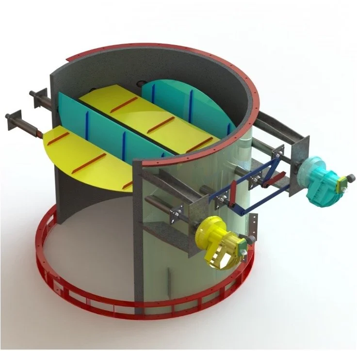
FIS Patented Efficiency Improvement Damper
A fired heater runs slightly below atmospheric pressure. The suction that makes this possible, the draft, is nothing more than buoyancy: the column of hot flue gas inside the radiant section and stack is lighter than the column of ambient air outside, and the weight difference shows up as negative pressure. Treating flue gas as air and using the ideal gas law, the density of a gas column is 2.70 × P/T in lb/ft³ (P in psia, T in °R), and converting the column-weight difference to inches of water (5.20 lb/ft² per in. w.c.) gives the working equation, with its constant no more mysterious than 2.70 divided by 5.20:
Draft ≈ 0.52 × H × P × (1/T_ambient − 1/T_gas)      (H in ft, P in psia, T in °R)

Stack gas at 300 °F vs 60 °F ambient:   ~0.46 in. w.c. per 100 ft
Stack gas at 400 °F:                    ~0.58 in. w.c. per 100 ft
Firebox gas at ~1,500 °F:               ~0.11 in. w.c. per 10 ft
That last line matches the rule of thumb in our published draft-control work: the radiant box gains draft at about 0.1 in. w.c. per 10 feet of box height, which is why the draft at the floor of a tall vertical-cylindrical heater runs around 0.3 to 0.7 in. w.c. The equation also says draft is never constant: it moves with firing rate, stack temperature, and ambient temperature. A cool night alone can add 0.1 in. w.c. or more of draft, which is exactly why a damper fixed in one position is wrong twice a day.
Where draft is spent, and why the arch is the point that matters
Draft is produced by the hot columns and spent crossing everything in the gas path: the convection bank's tube rows (the biggest consumer), the damper itself, and stack friction. Plot pressure against elevation and the profile pinches at one place: the radiant arch, the transition from radiant to convection section. As our published article puts it, the arch sees the highest absolute pressure anywhere in the heater except the stack tip. Everything below it is more negative; everything above it is spending the stack's draft.
That is why the arch is the control point. Hold the arch slightly negative and the entire heater is guaranteed negative; let it go positive and hot flue gas leaks outward through sight doors and casing joints, a hazard to people and a slow death for the casing and structure. The industry target, and the value API 560 requires stacks to be designed for, is a negative pressure of at least 0.10 in. w.c. at the arch. Our practice, published for two decades, is the same: hold about minus 0.1 in. w.c. at the arch in essentially all fired heaters.
The failure directions are both visible in the profile. Close the damper too far, or let the convection section foul, and the arch goes positive. Open it too far and the arch draft runs deep, the heater inhales air through every leak, and the excess air tax begins: as a rule of thumb, every 10% of extra excess air costs about 1% in efficiency, and even at $3 per million Btu, one square inch of leakage area can cost roughly $32,000 per year for each 0.1 in. w.c. of excess draft. Draft control is leak control.
The damper family
| Type | What it is | Where it fits |
|---|---|---|
| Butterfly (single blade) | One round or rectangular blade on a shaft | Round heater stacks; simple on/off and trim duty |
| Louver, parallel blade | Multiple blades rotating the same way | Large rectangular ducts; coarse control |
| Louver, opposed blade | Adjacent blades rotate opposite ways | Better control linearity; the choice where draft is actively controlled |
| Guillotine | A sliding blade that fully clears the bore | Tight isolation for maintenance; near-zero pressure drop when open |
| Diverter (flap or Tee) | Routes flow between two paths | HRSG bypass: sends turbine exhaust to the HRSG or the bypass stack |
On fired heaters the working choice is usually a butterfly or opposed-blade louver in the stack with a pneumatic operator. On HRSGs the family splits by job: diverters route the gas, guillotines isolate, and stack dampers hold heat in during standby, where trade guidance for cycling units explicitly recommends a closed stack damper to bottle up heat between runs.
What good damper control is worth
The published rules of thumb compound quickly: 10% excess air is about 1% of efficiency, and every 35 °F taken off the stack temperature is worth another 1%. One published FIS example put automatic draft control savings near $500,000 per year on a single heater. And on one distillate hydrotreater charge heater we revamped, a new convection section, stack, and pneumatic stack damper cut the flue gas temperature leaving the convection section by 202 °F and raised efficiency by 8.4%. The damper is what lets a revamped heater hold its new operating point. Read the case study
Can you name your arch draft right now? If not, or if it lives well past minus 0.1 in. w.c., send us your draft and O2 readings and an FIS engineer will give you an honest read on what a draft fix is worth. Tell us about your unit
Why conventional stack dampers disappoint
Most existing dampers were set up to fail on the drawing board, before the operator ever touched them.
They are oversized by design. The margins stack up. Process licensors add 10 to 20% to the heater duty when specifying. API 560 requires the stack and flue gas system to be designed for 120% of normal heat release while still holding that 0.10 in. w.c. negative pressure, on top of design excess air and design stack temperature. Stacks are sized for the hottest ambient day, 95 to 105 °F, when buoyancy is weakest. Designers commonly allow 1.5 velocity heads of damper loss where a fully open damper consumes only about 0.5. Stack height is often set by pollution dispersion and diameter by structural stability, not by process need. Add it up and the damper lands roughly twice as large as the flow requires; in the field it may sit 40 to 50% open at full load. In fluid-flow practice a control valve is deliberately selected one size smaller than the line, because an oversized valve has no control authority. Most stack dampers are the oversized valve.
Their control is non-linear. On an oversized damper, the first 20% of opening can pass 80% of the flow. All of the control lives in a sliver of travel, which makes fine draft adjustment nearly impossible by hand and unstable in automation.
They leak. Conventional dampers commonly carry a 1 to 2 inch gap between the blades and the refractory, which means 15 to 20% leakage even fully closed. On a cycling unit, that is the standby heat loss; on a running unit, it is a floor under how much draft you can trim.
So operators park them open. Old slide and louver dampers stick, their control is coarse, and operators are understandably reluctant to touch them, so most are left fully open. Our published survey work found heaters running at almost four times the recommended draft, and at the other extreme, heaters running positive at the arch. A more recent FIS survey of 25 heaters found excess O2 running 7 to 10% against a design target of about 3%. Either way the fuel bill pays: high draft pulls in tramp air through every opening, and the heater breathes whatever it wants, day and night, as ambient swings move the draft underneath a damper that never moves.
The signs your damper is costing you, in checklist form: operating excess O2 above roughly 4 to 5%, arch draft well below minus 0.1 in. w.c., a manual damper that lives fully open, or a stack visibly oversized for today's duty. If your unit checks two of these, the damper is worth an engineering look.
Where FIS fits
Draft control is one of the oldest problems in fired heater practice, and it is the problem our patented Efficiency Improvement Damper was built to solve. The design answers the failure modes above directly. Instead of one operator swinging all the blades, the damper uses multiple pneumatic operators, typically two and up to three on very large dampers: one set of blades closes to create the pressure drop that holds the correct arch draft, which restores control authority and lets the flow-versus-opening profile be customized to the heater, with smooth control from 50% to 115% load and the ability to open everything fully whenever needed, so nothing is given up. Seal plates eliminate the 15 to 20% leakage of a conventional damper.
The results on real heaters: one natural-draft crude heater went from 33% excess air to 15%, arch draft from minus 0.453 to minus 0.1 in. w.c., and efficiency from 79.0% to 82.3%, paying back in six months. A natural-draft cabin heater went from 6.8% excess O2 to 3.0% and gained 4.8 points of efficiency. On a natural gas heater in India, the fuel saving came to about $245,000 per year with 1,227 tons of CO2 avoided. Holding the correct arch draft continuously is what captures those savings, and the same draft physics and damper engineering carry directly to HRSG stack and isolation dampers on cycling plants. More on the damper, including a downloadable presentation and flyer.
The bottom line
A stack damper is a small piece of hardware in charge of a small number, and both are deceiving. Draft is made by buoyancy, spent in the convection section, and controlled at the arch, and the difference between a controlled arch and a neglected one is measured in percent of fuel, in casing life, and on cycling units in every restart. If you can name your arch draft right now, your damper is probably fine. If you cannot, that is worth a look.
FIS provides independent engineering, audit, and revamp services for fired heaters and HRSGs, including draft studies, damper engineering, and our patented Efficiency Improvement Damper. Contact us to scope a draft and damper review.
Related reading: Dampers and Draft Control in Cycling HRSG Plants and HRSGs and Fired Heaters: What Is the Same, What Is Different.