
Dampers and Draft Control in Cycling HRSG Plants
A short primer on the diverter, isolation, and stack dampers that decide how well a behind-the-meter HRSG plant starts, stops, and holds output, and why a turbine-centric design tends to get them wrong.
Why dampers matter more in a behind-the-meter plant
A baseload utility combined cycle starts a few times a month and runs flat. A behind-the-meter plant serving a data center looks different. It runs at high utilization, but it also cycles hard: it phases in as simple cycle first for speed, then adds the steam side; it carries N+1 redundancy, so units start and stop for one another; it takes maintenance windows scheduled to compute rather than to grid demand; and it ramps with site events. Every one of those transients runs through the plant's dampers and its draft system.
That is why the damper and draft scheme, which a utility plant can treat as a settled detail, becomes a live engineering problem on a cycling plant. Get it right and the plant starts fast, holds heat between runs, and protects turbine output. Get it wrong and the symptoms show up as slow restarts, thermal damage, and lost megawatts.
The dampers in a combined-cycle plant
Three damper functions do most of the work:
Diverter (bypass) damper. Routes the gas turbine exhaust either into the HRSG or straight up a bypass stack. It lets the turbine run in simple cycle for fast power while the HRSG is offline or warming, then brings the HRSG online in a controlled way. On a phased or redundant plant, this damper is exercised constantly.
Isolation and stack dampers. Seal the HRSG when it is not taking exhaust, to hold heat in for a fast restart and to stop reverse airflow from cooling the unit and drawing in moist air. Sealing quality, the leakage rate, is the difference between a warm restart and a cold one.
Fresh-air firing dampers. When the plant must make steam with the turbine off, isolation dampers plus a forced-draft fan and the duct burner run the HRSG on its own. The dampers shield the fan path from hot gas and direct the flow. Quick, reliable switchover is the whole point.
Draft and pressure drop are not free
Whatever the gas flows through on its way out, tubes, dampers, ductwork, costs the gas turbine output, because backpressure on the turbine reduces its power. A useful rule of thumb is that each 4 in. w.c. of gas-side pressure drop costs roughly 1% of turbine output.
GT output penalty ≈ (gas-side ΔP ÷ 4 in. w.c.) × 1%For a plant whose HRSG, dampers, and ductwork add 12 in. w.c.:
Penalty = (12 ÷ 4) × 1% = 3% of GT output
On a 200 MW turbine: 0.03 × 200 = 6 MW lost, continuously
Run that plant at high utilization and the lost output adds up:
6 MW × 8,000 hr/yr               = 48,000 MWh/yr
At a power value of $50/MWh       ≈ $2.4 million/yr
Tube banks set most of that pressure drop, but damper selection, duct geometry, and transitions are a controllable share of it. A damper chosen for first cost, or ductwork laid out for the building rather than the flow, quietly taxes the turbine for the life of the plant.
Where cycling plants get into trouble
The common thread in damper and draft problems is a design copied from a baseload utility plant and dropped onto a unit that cycles. The failure modes are predictable:
Slow restarts, because the HRSG was allowed to cool during standby when better damper sealing would have held it warm.
Thermal transients and condensate carryover during fast starts, when damper sequencing and drain logic are not designed together.
Reverse flow that cools the unit and pulls in moist air, when isolation is incomplete.
Lost turbine output from damper and duct pressure drop that was never minimized.
SCR and emissions performance that will not tune across the load range, because flow distribution was modeled at one duty point instead of the real duty cycle.
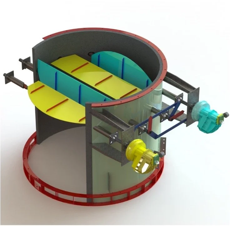
FIS Efficiency Improvement Damper
What good damper and draft engineering looks like
The fix is to engineer the damper and draft scheme against the plant's actual duty cycle, not a single design point. In practice that means dynamic draft and pressure modeling across startup, shutdown, standby, bypass, and fresh-air firing; damper sizing, sealing, and leakage specifications matched to how often the plant cycles; control and sequencing logic that is designed together with the drain and attemperator logic; and a deliberate effort to minimize the gas-side pressure-drop penalty rather than accept the OEM's standard duty assumption.
This is the work behind FIS's Efficiency Improvement Damper and our draft-control practice on fired heaters, where draft, excess air, and transient behavior have always had to be managed actively. The same dynamic draft modeling and damper-control engineering applies directly to HRSG diverter, isolation, and stack dampers, and it is most valuable on exactly the flexible, cycling, behind-the-meter plants now being built for data centers.
The bottom line
On a baseload plant, the damper and draft scheme is a detail. On a cycling, behind-the-meter plant, it decides restart speed, thermal stress, emissions tuning, and a measurable slice of turbine output. It is worth engineering against the real duty cycle, early, by someone who models draft and damper behavior for a living.
FIS provides independent engineering, audit, and revamp services for HRSGs and fired heat-transfer equipment for EPCs, IPPs, and data center energy teams, including draft and damper control engineering for cycling plants. To scope a draft and damper review, contact us here to email info@heatflux.com
This article is part of our HRSG engineering guide.