
Case Studies


No. 4 Reformer Heater Capacity Improvement
In October 2000, FIS carried out a Platformer Heater Revamp for a refinery located in South Texas.
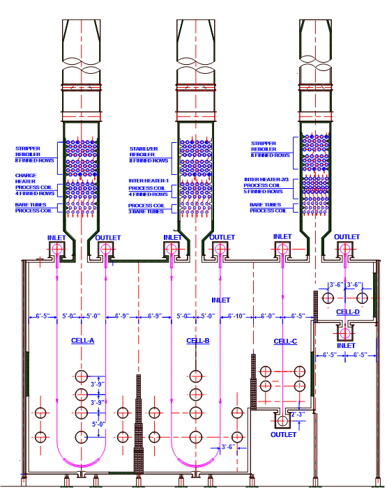
The four-cell Reformer Heater was originally designed for a total heat duty of 184 MMBtu/hr. The heater had process coils to process Naphtha + Recycle Gas, Stripper Reboiler, and Stabilizer Reboiler services. Client was facing heater performance issues as the heater was operating at reduced charge rate in each cell as compared to the original design.
The Process, Stabilizer, and Stripper Reboiler coils were absorbing low heat duties. All four cells were operating at very high excess air and low firing rates. Cell A/B and cell C/D were operating at 120% and 100% excess air, respectively. Client wanted to increase the capacity and improve the efficiency of this heater. However, steam generation or combustion air preheating was not desired. Client also wanted to increase absorbed heat duty of the Stripper and Stabilizer Reboilers.
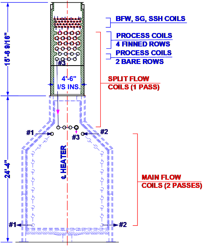
Capacity Improvement: The refinery approached the original designer of the heater. They proposed a conventional scheme to preheat the feed in the convection section. The scheme had four major drawbacks: Increased fluid pressure drop Required grade mounted stack Required large diameter piping Cost was very high "The installation costs were half compared to that of the conventional series flow design. The job was completed in October 2002 and has been running without any problems." FIS was solicited by the refinery to develop an economical scheme for increasing the capacity. FIS redesigned the heater with FIS patented Split Flow Technology. The Split Flow Technology aims to improve the utilization of thermal energy for process heating. This is achieved by splitting the process fluid into two parallel streams as- Main Stream and Split Stream. In Main Stream the fluid is heated in the radiant section. In Split Stream the fluid is heated in convection section. The two streams are combined at the heater outlet.
The heater was designed in such a way that process duty shifted to radiant section. This lowered the heat absorbed in convection section, thereby, yielding more heat absorption in the Stabilizer Reboiler & Stripper Reboiler coils. Proposed Heater (After Revamp) Proposed Heater (After Revamp)
Equalizing Pressure Drop: Split Flow Technology works on the concept of equal temperature difference and pressure drop in parallel streams. FIS installed orifices in the transfer lines (manifold Pipe) to equalize the pressure drop. The orifice provides restriction to fluid flow and increases the fluid pressure drop as required. The orifice size is selected based on required pressure drop to be achieved across orifice.
FIS carried out the entire scope of activities from conceptualization to commissioning of this heater revamp. The heater was successfully commissioned in October 2002. After revamp, the capacity of this heater was improved from 18,500 BPD to 24,000 BPD.
No.4 Reformer Heater NOx Reduction
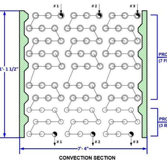
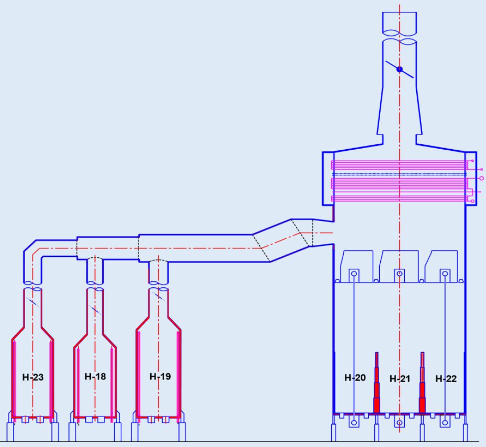
The No. 4 Platformer Heater, located at a refinery in South Texas, is a multi-cell Arbor coil heater consisting of a radiant section, a convection section and a stack. This heater is utilized to heat the feed entering the Platformer reactors. The platforming reaction is an endothermic reaction and occurs in four stages. The feed outlet of each stage reactor is reheated in the Platformer heater. The firing in these cells was accomplished by 36 numbers (before revamp) of natural draft burners located at the end walls on both the sides. These burners were originally designed for oil and gas combination firing. Refinery wanted to reduce the NOx emissions to 0.035 lb/ MMBtu (HHV) and address the high excess air requirement of the heater. FIS was approached to resolve this issue. FIS revamp scheme consisted of following:
Burners Replacement: Existing 36 numbers of natural draft burners were replaced with 44 Nos. of new Ultra Low NOx burners, to achieve lower NOx emissions at the heater stack. The NOx emissions were truncated to 0.035 lb/MMBtu. The number of burners were increased to reduce the heat release per burner and thereby reduce the flame lengths.
Stack damper: FIS noticed that the heater was poorly controlled. A very high draft at arch caused very high excess air to enter the heater. All three stacks were provided with cable and winch type manually operated damper to adjust the draft at arch. FIS provided opposed blade type pneumatically operated damper which are easily monitored and accessed. FIS designed the heater with required excess air as 15% in cell A/B and 30% in cell C/D. The stack dampers were provided to ensure that draft at arch level was maintained at the design value of (-0.1)” WC during all operating conditions.
Stack Modifications: The flue gases leaving the convection section enter the three individual stacks located above each convection cells. The existing 3 Nos. of stacks were retained with slight modifications. Lower module of the existing stack was modified to incorporate the new stack dampers and the upper module was amended to incorporate new reduced diameter stack tips. (conical shaped). This ensured that the flue gases were dispersed at a higher velocity than the existing.