
Duct Burners in HRSGs: A Practical Introduction
A short primer on supplementary firing for engineers and operators working with heat recovery steam generators.
What is a duct burner?
A duct burner is a gas burner installed in the flue-gas duct between a gas turbine and a heat recovery steam generator (HRSG). It uses the residual oxygen in turbine exhaust as combustion air, firing supplementary fuel directly into the gas stream to raise its temperature before it enters the HRSG. The process is called supplementary firing or duct firing.
Duct burners are a standard feature of combined-cycle and cogeneration plants where steam production needs to scale beyond what the gas turbine exhaust alone can produce.
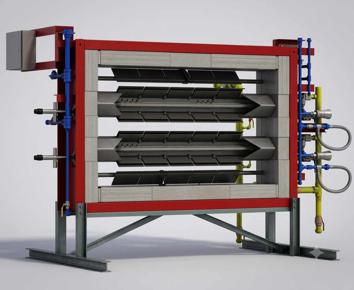
Image courtesy: Turbo Machinery Magazine
Why use one?
A gas turbine produces electricity but rejects significant high-grade heat into its exhaust. Older and mid-size machines typically exhaust at 450 to 550 °C (about 840 to 1,020 °F); large modern F- and H-class turbines run hotter, around 580 to 640 °C. An HRSG captures that heat as steam, but the steam quantity is fixed by the gas turbine's exhaust mass flow and temperature.
A duct burner decouples steam supply from gas turbine load. By burning additional fuel in the duct, an operator can:
Increase HRSG steam output by 30 to 50% (and more in some designs) on demand
Maintain steam supply when the gas turbine is at part load
Avoid the capital cost of a separate auxiliary boiler
Match steam delivery to a downstream process or absorption-chilled cooling load
Because the supplementary heat is added to a gas stream already passing through the HRSG, the marginal fuel-to-steam efficiency of duct firing is high: typically around 90% on a higher-heating-value (HHV) basis, and higher still on a lower-heating-value (LHV) basis, since nearly all of the added fuel's heat is absorbed by HRSG surface already in the gas path. On the same HHV basis, a standalone fired boiler is roughly 80 to 85%. (Overall combined-cycle electrical efficiency still falls slightly when duct firing, because the added fuel makes steam rather than turbine work; the comparison above is against a separate boiler, not against the unfired plant.)
How it works
Gas turbine exhaust typically contains 12 to 16% oxygen by volume. The turbine runs with large amounts of excess air to hold its firing (turbine-inlet) temperature within metallurgical limits, and that excess air leaves as oxygen in the exhaust. The residual oxygen is enough to burn additional fuel without supplying separate combustion air.
A simple heat balance establishes how much supplementary fuel is required to reach a target HRSG inlet temperature:
Q_supp = m_exhaust × Cp × (T_target − T_exhaust)Where:
Q_supp = supplementary heat duty (Btu/hr)
m_exhaust = gas turbine exhaust mass flow (lb/hr)
Cp = specific heat of the exhaust (≈ 0.26 Btu/lb·°F here; in practice it is closer to 0.27 to 0.28, rises with temperature, and depends on composition, so a rigorous balance uses enthalpy data)
T_target = desired HRSG inlet temperature (°F)
T_exhaust = gas turbine exhaust temperature (°F)
Worked example. A gas turbine exhausts at 1,000 °F with a mass flow of 1,000,000 lb/hr. The HRSG steam balance calls for an HRSG inlet temperature of 1,500 °F.
Q_supp = 1,000,000 × 0.26 × (1,500 − 1,000)
       = 1,000,000 × 0.26 × 500
       = 130,000,000 Btu/hr
       = 130 MMBtu/hr
To deliver 130 MMBtu/hr from natural gas with a Higher Heating Value (HHV) of ~1,000 Btu/scf:
Firing rate = Q_supp / HHV
            = 130,000,000 / 1,000
            = 130,000 scf/hr  (≈ 3.1 MMscf/day)
Oxygen check. Confirm the exhaust can actually support that firing rate. Methane combustion stoichiometry is:
CH4 + 2 O2 → CO2 + 2 H2OWork the check on a molar (volume) basis, because duct-burner oxygen limits are stated in volume percent:
Exhaust flow: 1,000,000 lb/hr ÷ ~28.8 lb/lbmol ≈ 34,700 lbmol/hr of flue gas
O2 available at a typical 16% by volume: 0.16 × 34,700 ≈ 5,560 lbmol/hr
Fuel burned: 130,000 scf/hr of methane ≈ 343 lbmol/hr, which consumes 2 × 343 ≈ 685 lbmol/hr of O2
O2 remaining: 5,560 − 685 ≈ 4,870 lbmol/hr in ~35,100 lbmol/hr of flue gas ≈ 13.9% O2 by volume
That leaves ~13.9% O2 by volume, adequate for a standard duct burner (which needs roughly 13 to 15%) and comfortable for a modern advanced low-NOx design, which can fire stably down to about 10.5% O2 without augmenting air. The margin is real but not large: if the exhaust had started at 14% O2 instead of 16%, the same firing rate would leave only ~12%, below what a standard burner can sustain without augmenting air, though an advanced low-NOx burner still could. The oxygen check, not just the heat balance, often sets the practical limit on how hard a duct burner can fire.
Types of duct burners
Two configurations cover most HRSG installations.
Linear (grid) burners. Runner elements (fuel-supply pipes fitted with gas injection ports) span the duct cross-section in a grid pattern. This is by far the most common design for combined-cycle and cogeneration HRSGs, because it distributes the flame evenly across the duct and produces a uniform temperature profile entering the tubes. The terms "linear," "grid," and "runner-type" all describe this same family.
Wall-fired (register) burners. Discrete, register-style burners mounted on the duct walls and firing inward, used mainly in smaller HRSGs or narrow duct geometries. These generally need a dedicated or augmenting-air supply rather than relying solely on exhaust oxygen. The same register arrangement is also used for fresh-air firing, where a forced-draft fan lets the HRSG run with the gas turbine off.
The right choice depends on duct geometry, available mixing length, firing temperature, and the required steam supply profile.
Key design considerations
1. Oxygen availability. A standard (legacy) duct burner needs roughly 13 to 15% O2 by volume for stable firing; modern advanced low-NOx designs use proprietary mixing to fire reliably down to about 10.5% O2 without augmenting air. Verify the available oxygen for off-design cases (wet compression, low ambient temperature, evaporative cooling, high exhaust moisture, and high duct-firing rates). Below the burner's limit, an augmenting-air fan or fresh-air firing is required.
2. Flow distribution. The flue-gas velocity profile across the duct must be reasonably uniform, typically within ±15% of the mean. Poor distribution causes hot spots, flame instability, and uneven heat absorption in HRSG tubes.
3. Mixing length. A minimum of 10 to 15 feet of straight duct is usually required between the duct burner and the first HRSG tube row to allow complete combustion and temperature uniformity.
4. Maximum firing temperature. Limited by HRSG casing, liner, and tube metallurgy. Standard internally-insulated supplementary firing is generally held to about 1,700 °F entering the tube bank; above that the casing liner can warp and expose the insulation, and the design moves toward furnace firing with a water-cooled membrane wall.
5. NOx control. Duct burners can be a meaningful NOx source. Modern designs use staged combustion and carefully tuned fuel/air mixing to keep NOx generation low. CFD modeling is often applied to optimize burner geometry for both thermal performance and emissions.
6. Turndown. Duct burners typically operate over a 5:1 to 10:1 turndown range. The lower limit is set by flame stability; the upper limit by maximum firing temperature and oxygen availability.
Duct burners in HRSG revamps
Most duct-burner engineering is not new construction; it is re-rating or replacing burners in existing HRSGs. Common revamp and retrofit triggers:
Capacity increase. Steam demand grows beyond the original design, and the duct burner must be re-rated or replaced to reach a higher firing temperature within the existing casing and tube limits.
NOx compliance. A tightening permit requires a lower-NOx burner, often with staged fuel injection and sometimes combined with downstream SCR.
Burner degradation. Cracked or warped runners, eroded nozzles, and refractory damage degrade the flame profile and steam quality, driving replacement.
Gas turbine change-out. A new or uprated turbine changes exhaust flow, temperature, and oxygen content, which shifts the firing margin and may call for a different burner pattern.
Each of these is an engineering problem upstream of the burner supplier. The duct-burner specification (sizing, burner pattern, oxygen margin, flow distribution, and emissions) determines whether the revamp performs. CFD modeling of the duct and burner is often the most cost-effective way to de-risk a revamp before fabrication.
The bottom line
Duct burners are the most flexible piece of equipment in a combined-cycle or cogeneration plant. They let an operator scale steam supply independently of gas turbine load, do it at higher marginal efficiency than a separate boiler, and avoid the capital cost of additional fired equipment. The engineering effort that goes into sizing, configuration, oxygen margin, and emissions control, whether at the design or revamp stage, is the single biggest determinant of how well a duct burner performs over the life of the plant.
FIS provides independent engineering, audit, and revamp services for fired heat-transfer equipment, including duct burners, HRSGs, and waste-heat recovery systems. To scope a duct-burner or HRSG project, contact us here or email info@heatflux.com
This article is part of our HRSG engineering guide.