CFD Modeling
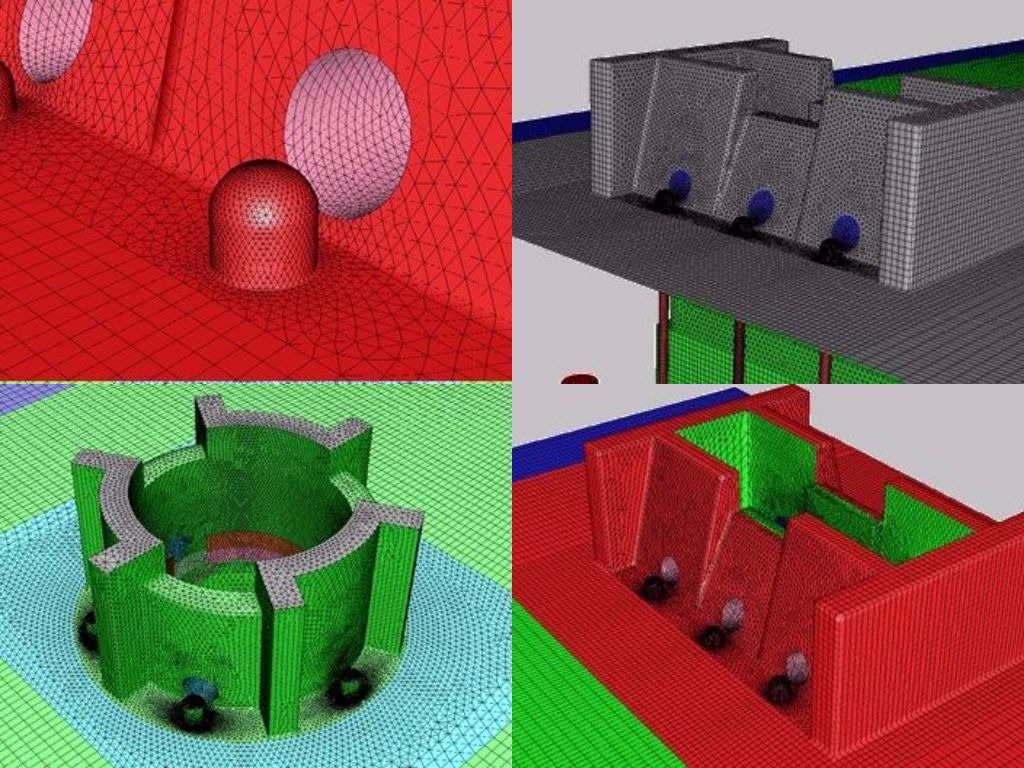
Computational fluid dynamic (CFD) modeling is an advanced simulation technology which is capable of performing detailed combustion analysis of burners to study the flow temperature profiles along with the flue gas circulation pattern in the heater. The simulation helps to understand the heater insights in terms of flue gas flow pattern, heat flux distribution over radiant tubes, tube metal temperatures, and temperature distribution in the heater.
At Furnace Improvements, we utilize CFD to study design and operating conditions of heaters, locate problems and provide solutions:
- Evaluate burner configurations, to improve heater performance
- Uniform air flow distribution across all burners
- Design of Ammonia Injection Grid to have uniform mixing
- Uniform process fluid distribution across transfer lines
- Reduce system pressure losses for ID fan suction and discharge side
This tool enables us to study the existing design and operating conditions of heaters and determine recommendations for solving any difficulties. CFD gives a competitive edge over other analyses due to its visual presentation of the observed conditions and proposed modification.


Case Study 1 : Optimizing Burner Layout by Combustion Analysis
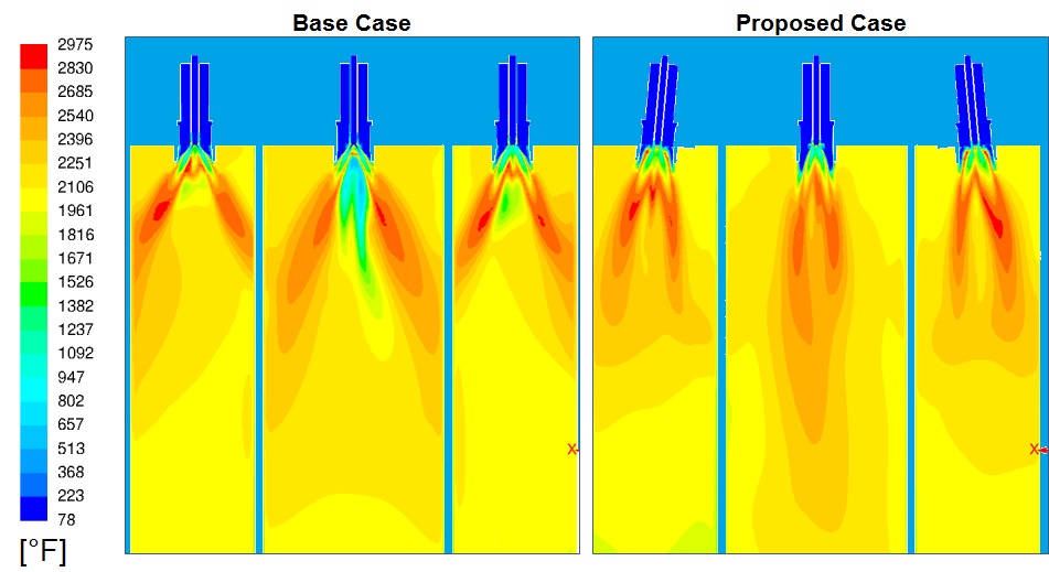
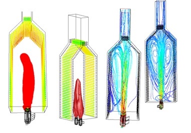 A cabin type crude heater was experiencing high tube metal temperatures in the top region of the heater. Hot flue gases were hitting the radiant tubes in the top region. Detailed combustion modelling simulations were carried out to match the field observations and identify the issue. Proposed burner layout was evaluated to check the improvement in flue gas flow patterns, flame profiles, radiant tube metal temperatures.
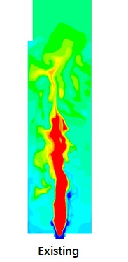
 Comparison of temperature profile shows that high temperature region is concentrated in the centre and the top radiant section is relatively cooler
Comparison of flame profiles and path lines show that proposed case flames are shorter and better flue gas circulation pattern in the heater to reduce radiant tube metal temperatures.
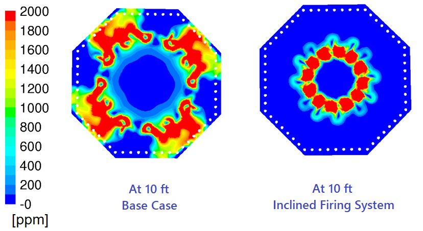
FIS has patented inclined firing technique which is effective in reducing the flame and flue gas impingement on radiant tubes. Inclined firing technique has been implemented in a vertical cylindrical vacuum heater, which had issues of high tube metal temperatures and flame impingement on the radiant tubes.
Temperature contours on various angular planes in the heater were compared for the existing and inclined firing case. Inclined firing clearly shows the flue gas temperatures around the radiant tubes is reduced which helped in increasing the run time of the heater.
Case Study 2: Lowering Radiant Tube Metal Temperatures with Inclined Firing
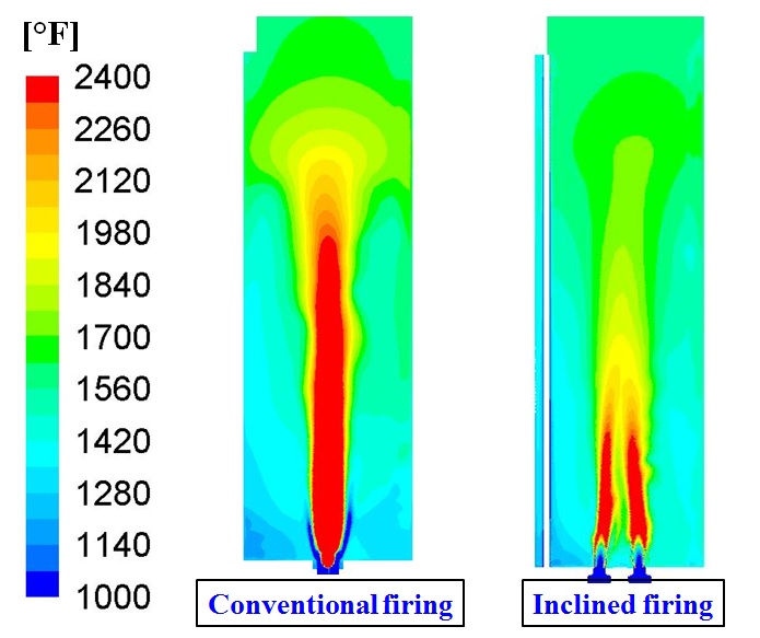
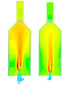
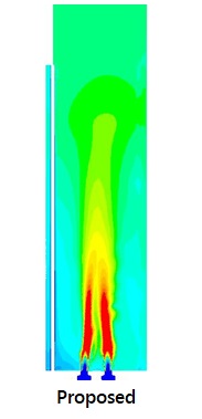
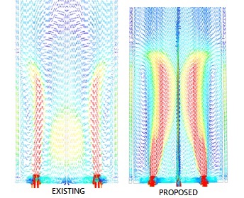 A vertical cylindrical heater was having high tube metal temperatures in the lower section of the heater. CFD simulations were carried out to understand the flue gas flow pattern and temperature profile in the heater. As the burners were placed at a larger burner circle diameter, a central down ward flow was set which pushed the hot flue gases towards the radiant tubes, leading to high tube metal temperatures. Modifications were proposed to reduce the burner circle diameter and installing the burners at an angle towards the centre of heater. Proposed modification improved the flue gas circulation pattern and reduced the radiant tube metal temperatures by 100 oF.
Flames for existing configuration are much wider and very near to the radiant tubes. Flames for inclined firing configuration are concentrated in the center of the heater, and away from the radiant tubes.
Case Study 3: Combustion Analysis of a Cabin Type Heater
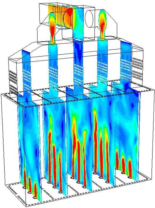
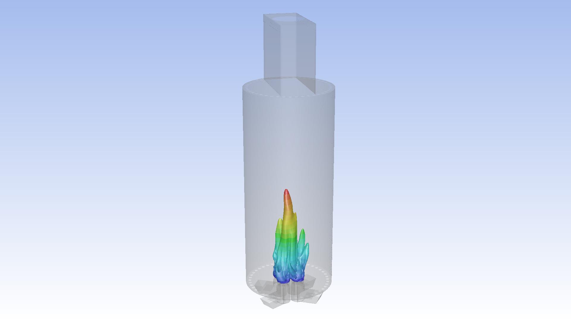
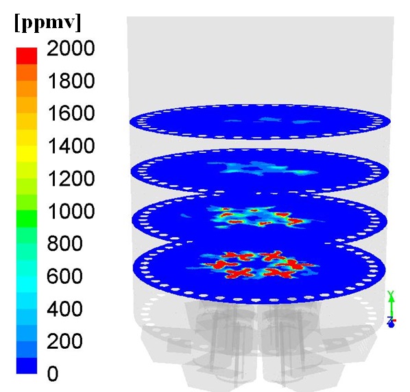
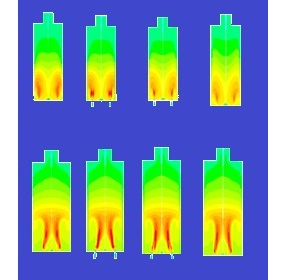
 A cabin heater had large burners installed which had issues with long flames, and high temperature flue gases hitting at the top region of radiant tubes. It was proposed to replace large burners with smaller burners. Each burner was replaced by four smaller burners to have equivalent total heat release. Smaller burners reduced the flame height considerably, also the heat distribution was more even in the heater. In order to further improve the heat distribution, burners were inclined towards each other. This helped in moving the flames further away from radiant tubes.
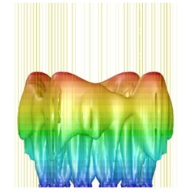
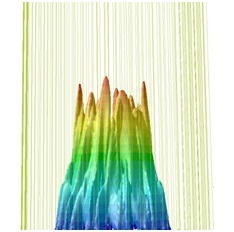
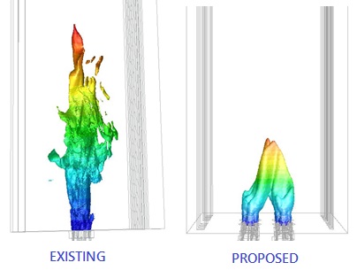 Existing burner configuration has longer and wider high temperature zone. Proposed smaller burners had shorter high temperature zone.
Flame of existing large burner configuration is much wider and very near to the radiant tubes. Flames for smaller burners are concentrated in the center and away from the radiant tubes.
Case Study 4: Improving Air Flow distribution across all burners
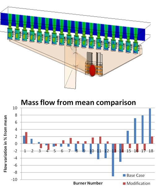
 CFD simulations help to understand the air flow pattern and evaluate the various design modifications to achieve uniform air flow distribution across all the burners. CFD results provide insight on placing the turning vanes, modifying the duct shape or the need of perforated plates.
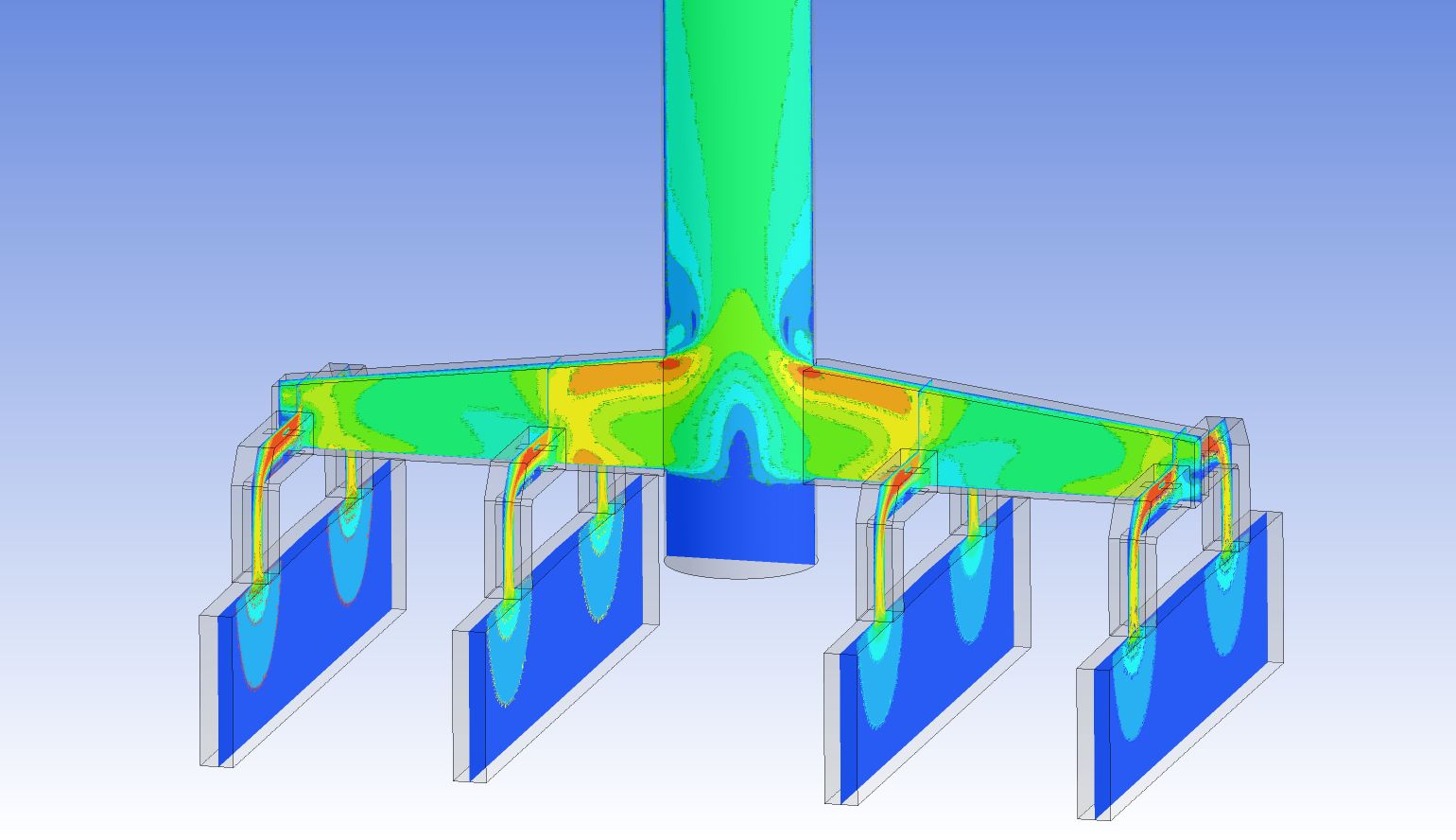
Air flow distribution for an atmospheric charge heater: There are 18 burners firing vertically up having a single burner plenum, with combustion air duct in the bottom. For the existing case, centre burners were experiencing low air flow rate and the end burners were receiving very high air flow rate. Various designs of installing turning vanes, baffles were evaluated to minimize the mal-distribution of air flow rate across all the burners.
Case Study 5: Reducing System Pressure Losses for ID Fan
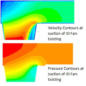
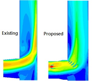
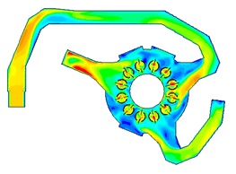
 Sudden sharp 90o bends at inlet and outlet of ID Fan causes high pressure losses which in turn reduces the overall capacity of the heater or demands for a higher rating fan. CFD simulations provide insight of the flow profile and region of high and low velocity region causing most of the pressure drop in the system.
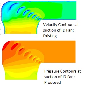
Installing turning vanes and minor modifications to the inlet duct of ID Fan, uniform flow distribution was achieved at the inlet and pressure drop was reduced by 0.5 inches w.c.
On the ID Fan discharge side, the flow come out through the fan outlet with a typical flow profile, which has higher air velocity in the top and lower velocities in the bottom region. Baffles are installed in the inlet duct upstream of the bend in addition to the turning vanes in the bend to improve the flow distribution and reduce the system pressure losses. A reduction of about 0.5 inches w.c. was obtained by making minor modifications to the duct and installing turning vanes in the stack.